
Computers are often described as machines that understand only zeros and ones. The wording makes binary sound like a limitation of their intelligence. It is more useful to think of it as a choice about how to represent information reliably. Engineers need the next part of a circuit to recognise the intended value even when the physical signal is imperfect. 1
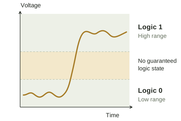
A bit does not need one exact voltage
Imagine a hypothetical system that accepts voltages below 0.8 volts as a logical 0 and above 2.0 volts as a logical 1. A change from 0.2 to 0.3 volts leaves the interpretation unchanged. The middle region is outside the guaranteed valid-input ranges. These numbers are just an example, not a specification for every chip. 1
Designers also leave room between the levels an output guarantees and the levels the next input accepts. That room is a noise margin. A sufficiently small disturbance can then occur without changing the bit the receiving circuit recognises. 1
Two states can represent more than two things
One bit has two possible values. Two bits have four possible patterns: 00, 01, 10 and 11. A third bit doubles the number again, because it can be either 0 or 1 for every existing pattern. With eight bits there are 256 different patterns. The capacity comes from combinations, rather than from asking one signal to distinguish 256 separate levels. If those eight bits represent an unsigned whole number, the possible values run from zero to 255. Representing 256 needs a ninth bit. An extra place doubles the available patterns; it does not add just one more value.
Binary numbers use place value, just as decimal numbers do. The places in decimal represent ones, tens and hundreds; binary places represent ones, twos, fours, eights and so on. Reading 1101 as an unsigned binary integer gives 8 + 4 + 0 + 1, or thirteen. The written form is longer than 13, but that is an inconvenience for people reading it, not a requirement for a circuit to become more precise. Leading zeros can fix the width of a field without changing the unsigned number it represents. Adding one to 1111 gives 10000: the binary counter carries into a new place, just as a decimal counter does when 99 becomes 100.
Making the states do useful work
Modern digital circuits commonly use MOSFETs, a kind of transistor whose conducting behaviour is controlled by voltage. Under suitable operating conditions, engineers can model them as switches. In CMOS logic, complementary arrangements of transistors connect an output towards a low or high supply level. An inverter, for example, produces a logical 1 from a valid 0 input and a logical 0 from a valid 1 input. 2
The switch model is an approximation with conditions. Transistors do not change state instantaneously, and the circuit has electrical limits. Engineers must account for timing as well as the values a gate is meant to produce. A correct truth table alone does not guarantee that a physical implementation will work at any chosen speed. 2
Why switches and logic fit together
Long before today's chips, relay circuits made connections using moving contacts. Claude Shannon's work on relay and switching circuits showed how their behaviour could be analysed using an algebra closely related to symbolic logic. Designers could describe the required behaviour mathematically and use that description to construct or simplify a circuit. 5
A simple example is a lamp controlled by two switches in series: both must be closed for current to pass. That corresponds to an AND condition. Parallel branches can provide an OR condition, because either branch can complete the path. More complicated networks can therefore implement combinations of logical decisions. The mechanism changed as electronics developed, but the usefulness of representing and combining discrete conditions remained. 5
The same bits can mean different things
A pattern does not explain its own meaning. The bits 01000001 can be interpreted as the unsigned number sixty-five. In ASCII-compatible UTF-8 text, that byte represents the capital letter A. Unicode assigns numbers called code points to characters and other text elements. UTF-8 represents the permitted code points using one to four bytes. The interpretation depends on an encoding agreed by the software reading and writing the data. 3
The same bytes can be decoded incorrectly if a program assumes the wrong text encoding. A UTF-8 file read using a different encoding can show the wrong characters even though none of its bytes has changed. The file needs an agreed interpretation as well as reliable storage. 3
Some hardware uses more than two physical states
Binary does not require every individual component to store only one bit. NAND flash provides a useful counterexample. Single-level-cell flash stores one bit per cell, while multilevel designs can store two, three or four bits per cell. Micron's NAND documentation distinguishes these options and the trade-offs among capacity, performance and endurance. 4
Storing four bits requires distinguishing sixteen possible patterns in one cell. More information fits into the same cell, but the device needs to distinguish more physical states. The data presented to software can still be a sequence of bits. Logical representation and physical storage are different levels of the design. 4
Sources
- MIT Computation Structures: The Digital Abstraction (opens in a new tab)
- MIT Computation Structures: CMOS Technology (opens in a new tab)
- Unicode: UTF-8, UTF-16, UTF-32 and BOM FAQ (opens in a new tab)
- Micron: Choosing the right NAND (opens in a new tab)
- Claude Shannon: A Symbolic Analysis of Relay and Switching Circuits (opens in a new tab)